Seems like a lot of effort. Why?
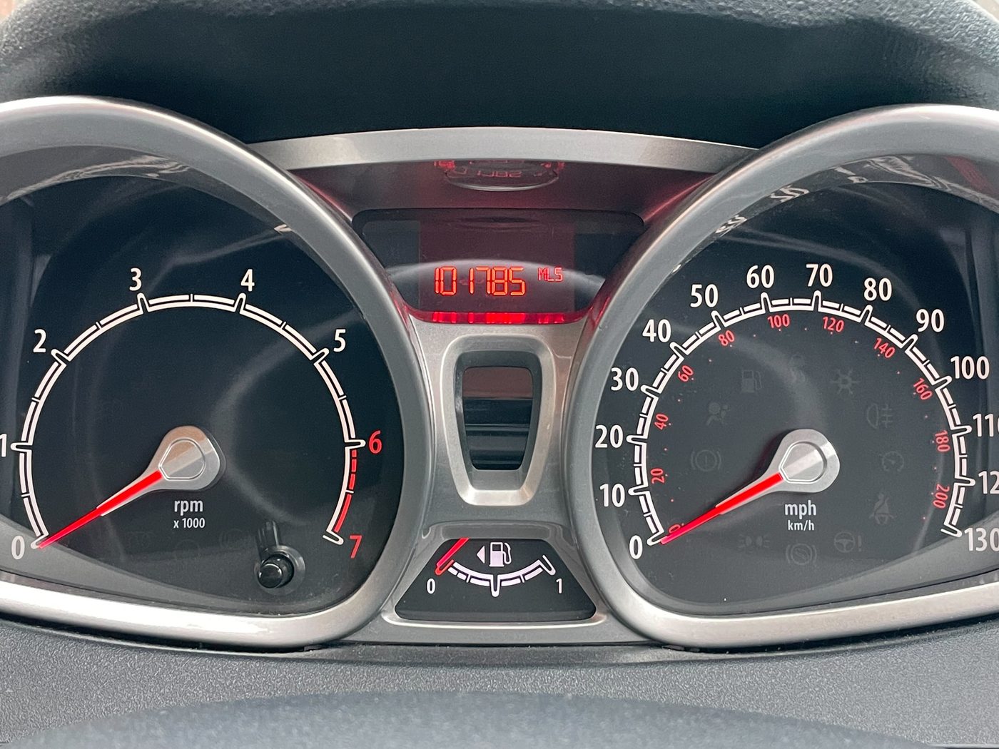
Back in the sands of time, I owned an Alfa Romeo 159. Beautiful car, but it overheated on the day I bought it. The dealer that sold it to me was not interested in helping me get that resolved, and so it was down to me, a young guy with no money to get it sorted out and back on the road. Since then, I've watched every water temperature gauge in every car I've ever driven like a hawk! But in the Fiesta, a basic model of car, there is no water temperature gauge fitted as standard.
Initial Approach
In a previous job, I was tasked with connecting to a vehicle's CAN bus system from an Android application in order to retrieve data from the vehicle. And it was this idea that I wanted to implement for myself. I had a suspicion that a water temperature sensor was available to me, even if there was no gauge, as the Fiesta is equipped with an 'overheat' warning lamp. The car must somehow know to trigger that warning.
I bought an ELM327 Bluetooth dongle and wrote a simple Python app on my laptop. I was able to use a library called pyOBD to write a few lines, plugged in the dongle to the OBDII port, paired my laptop with it and hey presto! I had a water temperature reading. Now I knew that it was possible - it spurred me on further!
At this point, I did write an app on a Raspberry Pi that used the Bluetooth dongle and displayed the temperature on a screen. It was great - a huge feeling of success when I finally got that working, but it was a clunky solution, the Pi was plugged into the cigarette lighter, without enough voltage, the equipment was rolling around inside my car and there wasn't a nice place to fix it anywhere - it just wasn't a nice hardware solution. The other problem was that the Bluetooth dongle needed to be constantly plugged into the OBDII port, and that bothered me. I wanted something better - I wanted OEM plus.
A Better Approach
I also sort of felt like I'd just taken the easy way out by using Bluetooth. A real, nice, OEM+ looking integration would tap into the CAN bus itself, and not use a 3rd party dongle for data. I was also concerned that someone could in theory connect to my dongle somehow and send CAN data to my ECU while I was driving...you may call me paranoid - but I like to be on the safe side!
So the real project began. My requirements were:
- Use data directly from the CAN bus
- Integrate the solution somewhere nice in the car, without exposed wires or other hardware on display
- Not take up any USB power sockets
- Not occupy the ODBII port
The Hardware
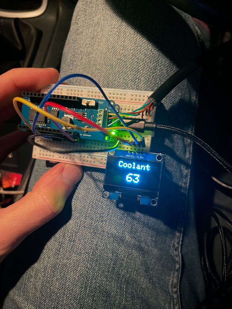
- Arduino MKR Wifi 1010
- Arduino MKR CAN shield
- 1.3" LCD with OLED display SSH1106
The Code
Firstly, the Arduino sketch code that runs the top-level program:
#include <CAN.h>
#include <SPI.h>
#include "DisplayManager.h"

#define CAN_FAILED 0
#define CAN_OK 1

#define OBD_RESPONSE_ID 0x7E8
#define OBD_COOLANT_TEMP_ID 0x05

void setup() {
  Serial.begin(9600);

  if (!initDisplay()) {
    Serial.println("Could not start display - program ending.");
    while(1);
  }

  configureCanConnection(500000);

  drawSplashScreen();

  delay(2000);
  writeTemperature("--");
}

void configureCanConnection(int speed) {
  if (CAN.begin(speed) == CAN_FAILED) {
    writeError("Starting CAN failed.");
    delay(3000);

    configureCanConnection(speed);
  }

  CAN.filter(OBD_RESPONSE_ID);
  CAN.onReceive(canResponseReceived);
}

bool sendTemperatureRequest() {
  CAN.beginPacket(0x7DF);  // 0x7DF is the broadcast request ID for OBD-II
  CAN.write(0x02);  // Number of additional data bytes (2)
  CAN.write(0x01);  // Service ID for "Show Current Data"
  CAN.write(0x05);  // PID for Engine Coolant Temperature
  CAN.write(0x00);  // Padding bytes to reach 8 bytes total
  CAN.write(0x00);
  CAN.write(0x00);
  CAN.write(0x00);
  CAN.write(0x00);

  return CAN.endPacket() == 1;
}

void loop() {
  if(sendTemperatureRequest()) {
    Serial.println("Request sent");
  } else {
    Serial.println("Request failed to send");
  }

  delay(1000);
}

void canResponseReceived(int packetSize) {
  long packetId = CAN.packetId();

  if(packetId != OBD_RESPONSE_ID) {
    Serial.println("Received unexpected CAN message");
    return;
  }

  Serial.println("Received " + String(packetId));

  byte response[8];
  int index = 0;

  while (CAN.available()) {
    response[index++] = CAN.read();
  }

  if (response[1] == 0x41 && response[2] == OBD_COOLANT_TEMP_ID) {
    int temperature = response[3] - 40;  // Apply the formula A - 40
    writeTemperature(String(temperature));
  } else {
    Serial.println("Unexpected packet format received");
  }
}
Then, the DisplayManager.cpp code that is in charge of dealing with the specific display in use.
Note my nod to Aston Martin's Power, Beauty, Soul...
#include "DisplayManager.h"

GyverOLED<SSH1106_128x64> display;

bool initDisplay() {
  display.init();
  return true;
}

void drawSplashScreen() {

  display.clear();
  display.setScale(1);

  display.setCursorXY(35, 30);
  display.print("NO POWER");
  delay(1000);
  display.update();

  display.setCursorXY(40, 40);
  display.print("NO BEAUTY");
  delay(1000);
  display.update();

  display.setCursorXY(45, 50);
  display.print("NO SOUL");
  delay(1000);
  display.update();
}

void writeTemperature(String temperature) {
  display.clear();

  display.setCursorXY(47, 30);
  display.setScale(1);
  display.print("WATER");

  int xOffset = 0;
  switch(temperature.length()) {
    case 1:
      xOffset = 56;
      break;
    case 2:
      xOffset = 50;
      break;
    case 3:
      xOffset = 44;
      break;
  }

  display.setCursorXY(xOffset, 45);
  display.setScale(2);
  display.print(temperature);
  display.update();
}
You'll notice that there are a lot of hardcoded constants in this code around the x and y position. This is because I am tuning exactly where the text sits on the screen so it fits perfectly within the hole that I drilled in the window switch. This is not directly reusable code!
And its header:
#include <GyverOLED.h>

bool initDisplay();
void writeTemperature(String temperature);
void writePlaceholder();
void drawSplashScreen();
The Installation
It took a while to decide where the locate the display. The interior of the Fiesta is quite curved, without much spare space on a flat surface visible from the driver's seating position.
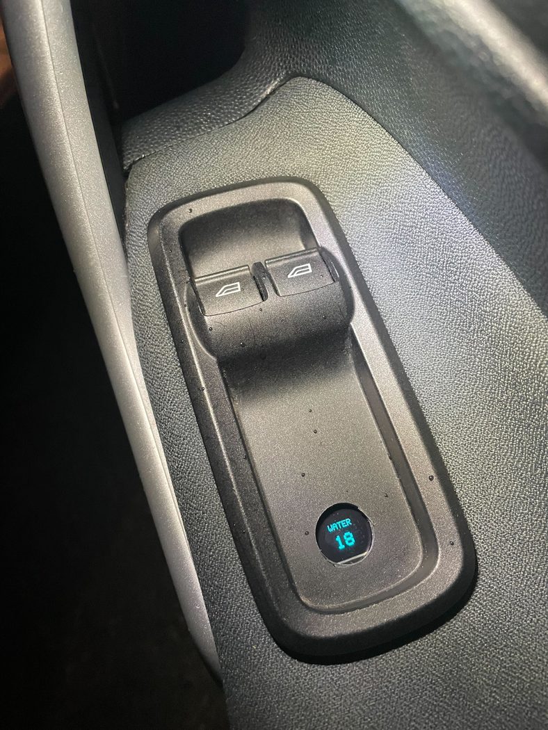
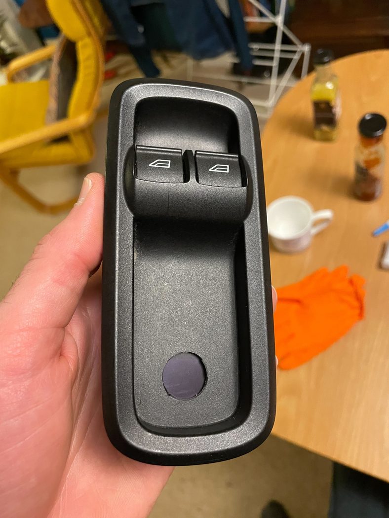
The best place I could think of was inside the blank plastic space behind the driver's window controls inside the door card. Popping off this switch body, I could see that there was a hollow space inside the door where I could fit the hardware. Also, I would need to find a way to pass the CAN bus wires into the door as they were not part of the door wiring loom already.
I drilled a large hole into the plastic window switch body, then glued and screwed my display onto the back.
Wiring
I picked up ignition-switched power from the window switches using a couple of Wago connectors. This means that the device only runs when the ignition is switched on, and doesn't continue to run once the car is switched off.
The CAN bus wires proved more tricky. After establishing that the CAN bus network was not already available inside the door, I racked my brains as to how I could pass through the wires. I considered using a wireless connection again (hello Bluetooth my old friend), but I stuck to my guns and pursued a hard-wired approach.
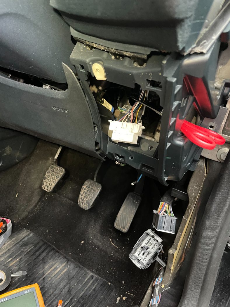
There is already a connector that passes wires through from the inside car loom to the door loom. There were a number of spare connection slots on those connectors - the problem was just going to be finding what connectors they were, and then buying the appropriate crimp tools etc...but then - a brainwave!
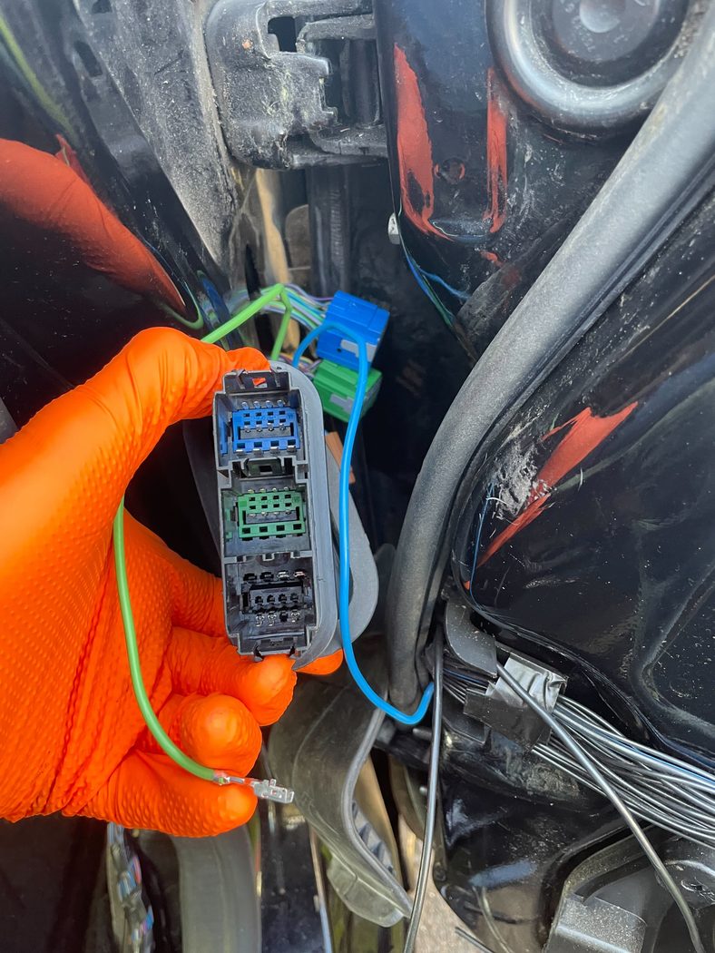
I went on eBay and bought a second-hand door loom from another Fiesta with all the wires and connectors still attached. I found wires with connectors of same gauge, cut them off the old loom and soldered them onto some new wires both inside the car to pick up the CAN bus and then inside the door to pass the CAN data to my Arduino. That way, I could use some spare slots on the existing connectors to pass the wires through from the inside of the car to the door, cleanly transferring data through an existing connector.
After that, it was a long, drawn-out process of packaging - cutting, soldering and heatshrinking wires until the loom was complete. I fixed the Arduino to the door itself, not the door card, using a sticky-backed breadboard. Everything is designed to be disconnectable if the door card needs to be removed in future.
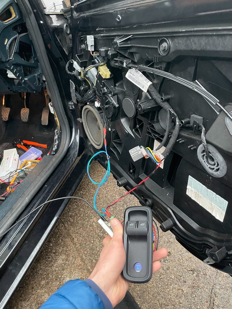
The Results
The temperature gauge works every single time I use the car - this is what I love about embedded software. It has no dependencies that break on you, Windows update don't come in and spoil things - it's a controlled environment that I can now enjoy for as long as I own the car. And, I get the extra glory of actually finishing a personal project, which is not something I often celebrate!